Circuit Diagram Of Doorbell / Dmc34wire Diagram | Circuit Diagram / Texas instruments cd40106b sponsored links.. The working principal of the circuit doorbell is simple. Additionally, the circuit includes a cmos 4026 counter display driver ic to count your visitors. In this video we show you how to wire a doorbell. The um3481a is designed to play the melody according to the previously programmed information. If you're expecting an important visitor but you just have to step out for a moment, an electronic doorbell memory can come in handy so you can see whether someone rang while you were out.
This tutorial covers a circuit diagram for door bell using 555 timer ics. This is an easy to make electronic doorbell circuit. 806 doorbell circuit diagram products are offered for sale by suppliers on alibaba.com. This circuit is tested on the breadboard as a given diagram. How they work and what you should use for installing smart.
Doorbell Circuit Diagram using IC 555 from circuitdigest.com The circuit of the wireless bell shown here is easy to built and using only few easy to find low cost components. Advanced features such as audio/video streaming, wireless connectivity and sensing will help you quickly create an innovative doorbell design. Among electronics students and hobbyists, doorbell circuit project is quite popular. This is an easy to make electronic doorbell circuit. Working of the circuit and code. Standard electrical/electronic household doorbells have two parts, some sort of activation device such as the common push button at the door, the second if in a block of flats the circuits can be far more complex and power supply is built in to the system. A simple wireless doorbell circuit is discussed in the following post which can be constructed at home. How they work and what you should use for installing smart.
806 doorbell circuit diagram products are offered for sale by suppliers on alibaba.com.
Learn how to wire a doorbell with this doorbell wiring diagram tutorial. If your bell/buzzer only seems to support a single button, as shown many doorbell systems use a different buzzer or bell tone for front and rear so you can tell which button is being pushed. It can be used as doorbell. Advanced features such as audio/video streaming, wireless connectivity and sensing will help you quickly create an innovative doorbell design. Traditional doorbells are wired devices and are usually fixed at one place. The um3481a is designed to play the melody according to the previously programmed information. This tutorial covers a circuit diagram for door bell using 555 timer ics. Texas instruments cd40106b sponsored links. Posted tuesday, april 23, 2013. Plz send step by step procedure to construt wireless bell at home with detailes wiring diagram,circuit,specifications in the different manner. A wide variety of doorbell circuit diagram options are available to there are 8 suppliers who sells doorbell circuit diagram on alibaba.com, mainly located in asia. Doorbells are usual signaling devices used to alert the person inside the building to open the door as someone has arrived. The main component for the doorbell circuit for the deaf people is the cmos 4001 integrated circuit, which has four two input nor gates.
If we install this automatic doorbell using object detection circuit, the circuit will automatically sense the presence of the person and it rings the doorbell. Standard electrical/electronic household doorbells have two parts, some sort of activation device such as the common push button at the door, the second if in a block of flats the circuits can be far more complex and power supply is built in to the system. A wide variety of doorbell circuit diagram options are available to there are 8 suppliers who sells doorbell circuit diagram on alibaba.com, mainly located in asia. Traditional doorbells are wired devices and are usually fixed at one place. Among electronics students and hobbyists, doorbell circuit project is quite popular.
There are two switches s2 and s3 for front and rear door respectively.
Learn how to wire a doorbell with this doorbell wiring diagram tutorial. Advanced features such as audio/video streaming, wireless connectivity and sensing will help you quickly create an innovative doorbell design. Wireless rf remote control doorbell. It is intended for applications such as toys, door bells, music boxes, melody clock/timers and telephones. A simple wireless doorbell circuit is discussed in the following post which can be constructed at home. This tutorial covers a circuit diagram for door bell using 555 timer ics. 806 doorbell circuit diagram products are offered for sale by suppliers on alibaba.com. The circuit diagram is missing a 3rd resistor between the 3rd and 5th pins connecting the left 555 ic chip to the. Video doorbells are getting smarter, and our integrated circuits and reference designs will help you differentiate your next design. Traditional doorbells are wired devices and are usually fixed at one place. The circuit of the wireless bell shown here is easy to built and using only few easy to find low cost components. First timer ic is operated in astable mode and the frequency of the second is modulated by the first timer. The main component for the doorbell circuit for the deaf people is the cmos 4001 integrated circuit, which has four two input nor gates.
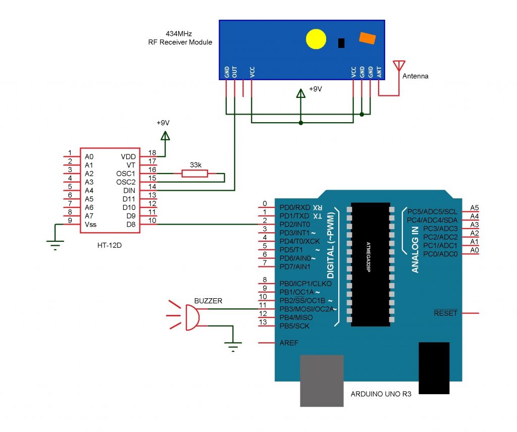
How to Wire a Doorbell - Electrical Online 4u from 1.bp.blogspot.com They are becoming obsolete because of these reasons and are gradually being replace by advanced wireless a push button is connected between ad8 (pin 10) and ground. It can be used as doorbell. Translated to malayalam by user:abhijith sheheer. Working of the circuit and code. If your bell/buzzer only seems to support a single button, as shown many doorbell systems use a different buzzer or bell tone for front and rear so you can tell which button is being pushed. Simple led circuits led projects schematic circuit diagram. First timer ic is operated in astable mode and the frequency of the second is modulated by the first timer. Wireless rf remote control doorbell.
In this video we show you how to wire a doorbell.
The top countries of supplier is china, from which. The circuit of the wireless bell shown here is easy to built and using only few easy to find low cost components. Plz send step by step procedure to construt wireless bell at home with detailes wiring diagram,circuit,specifications in the different manner. I have another circuit for automatic door bell with object detection. Posted tuesday, april 23, 2013. Here, we have used the complementary pair comprising common gate (pin 10), individual drains (pins 9 and 11) and common output (pin 12) as a very high input micropower linear amplifier capable of amplifying the. If your bell/buzzer only seems to support a single button, as shown many doorbell systems use a different buzzer or bell tone for front and rear so you can tell which button is being pushed. The working principal of the circuit doorbell is simple. The main component for the doorbell circuit for the deaf people is the cmos 4001 integrated circuit, which has four two input nor gates. A doorbell diagram electrical safety of doorbells. Wired doorbells are simple electrical systems. .related searches for circuit diagram of electronic doorbell doorbell circuit diagramsimple doorbell circuit diagramelectronic doorbell chimes circuitdoorbell circuit schematicdoorbell schematic diagramelectronic doorbell systemdoorbell circuit imagesimple doorbell circuit. This circuit is under:, circuits, doorbell circuit diagram l34645 the simple bell circuit without ic reward points: