Home › Unlabelled ›
Reading A Schematic Diagram - Diagram How To Read Building Wiring Diagram Full Version Hd Quality Wiring Diagram Diagramsaray Candyarena It - Hey everyone, this seems like (and is) a very nooby question, but everyone needs to start somewhere, right?
Reading A Schematic Diagram - Diagram How To Read Building Wiring Diagram Full Version Hd Quality Wiring Diagram Diagramsaray Candyarena It - Hey everyone, this seems like (and is) a very nooby question, but everyone needs to start somewhere, right?. Although schematic diagrams are commonly associated with electrical circuits, many examples can be found in other industries. Upon completion of this chapter the student will be able to:. Learn vocabulary, terms and more with flashcards, games and other study tools. They allow circuits to be 'followed through' when tracing faults. Start studying chapter 6 reading schematic diagrams.
Reading schematics (circuit diagrams) part 1. Laptop schematic diagram is tough to read yet very productive and essential when it comes to motherboard repairing. Across the world, car and motorbike owners use instruction. Product data a global reference guide for reading schematic diagrams. A circuit diagram, or a schematic diagram, is a technical drawing of how to connect electronic components to get a certain function.
Reading Schematics from www.zen22142.zen.co.uk Each of the lines are wires. In fact, if you can read a schematic, you can build a circuit before even understanding how it. Apr 20, 2012, 01:48 am. Very easy to understanding when you read. Learn vocabulary, terms and more with flashcards, games and other study tools. Schematic diagrams show the circuit flow with its impression rather than a genuine representation. To read and understand an electronic diagram or electronic schematic, the basic symbols and conventions must be understood. Electronic prints fall into two basic categories, electronic schematics and block diagrams.
A schematic diagram is a picture that represents the components of a process, device, or other object using abstract, often standardized symbols and lines.
So lets dissect this circuit! To read and understand an electronic diagram or electronic schematic, the basic symbols and conventions must be understood. The most common schematic diagram is found in large cities as the subway map. Schematic diagrams describe the main and auxiliary circuits for control, signalling, monitoring and protection systems. All of the individual components make sense to me, however the diagram does not. Such schematics are often not to scale and use symbols rather than realistic images. They are drawn in sufficient detail to explain to the user the circuitry and its mode of operation. A schematic, or schematic diagram, is a representation of the elements of a system using when creating a schematic, it's important to make sure you're illustrating your circuit with the proper level of abstraction. Learning to read electrical schematics is like learning to read maps. Electronic schematics represent the most detailed category of. Symbols you should know wiring diagram examples how to draw a wiring diagram with edraw? Read and interpret the schematic a dehumidifier slideshow 1752487. Components with many pins are often represented by multiple schematic symbols simply to allow for readable schematics.
So lets dissect this circuit! Help reading a schematic diagram. Papers » principles of schematics etc. Schematic diagrams describe the main and auxiliary circuits for control, signalling, monitoring and protection systems. Although schematic diagrams are commonly associated with electrical circuits, many examples can be found in other industries.
Reading Iphone Schematics Pdf Updated Information On Iphone 2019 from phonerepairingsolutions.com If you're just trying to convey a. Schematic diagrams show the circuit flow with its impression rather than a genuine representation. Type of wiring diagram wiring diagram vs schematic diagram how to read a wiring diagram: Such schematics are often not to scale and use symbols rather than realistic images. A schematic, often referred to as 'schematic diagram or block diagram', is a way to represent the elements of any system or electronics by using the symbols, graphics and. Circuit diagrams, aka schematics, are line drawings that show how a circuit's components are connected together. Its symbol reflects this characteristic: Learning to read electrical schematics is like learning to read maps.
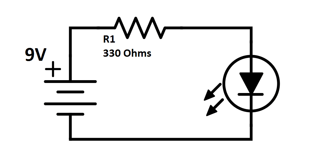
Starting with a very simple circuit and components.
Product data a global reference guide for reading schematic diagrams. The electronic schematic or circuit diagram is in some ways simpler. Reading schematics is actually pretty easy. Across the world, car and motorbike owners use instruction. Each symbol represents an electronic component in a logical sense (not its appearance) like the circle for a station on the. A circuit diagram (electrical diagram, elementary diagram, electronic schematic) is a graphical representation of an electrical circuit. Although schematic diagrams are commonly associated with electrical circuits, many examples can be found in other industries. Each of the lines are wires. Schematics are the functional diagram of electronic circuits. Schematic diagrams show the circuit flow with its impression rather than a genuine representation. With so many designs available on the web, understanding how to read schematics can unlock a world of possibilities for the electronics maker. Electronic prints fall into two basic categories, electronic schematics and block diagrams. A schematic in electronics is a drawing representing a circuit.
Electronic prints fall into two basic categories, electronic schematics and block diagrams. Apr 20, 2012, 01:48 am. They are drawn in sufficient detail to explain to the user the circuitry and its mode of operation. If you want to build the circuit, you only. The most basic symbol is a simple conductor, shown simply as a line.
How To Read Electrical Schematics Circuit Basics from www.circuitbasics.com If you're just trying to convey a. Start studying chapter 6 reading schematic diagrams. Hey everyone, this seems like (and is) a very nooby question, but everyone needs to start somewhere, right? Circuit diagrams, aka schematics, are line drawings that show how a circuit's components are connected together. Components with many pins are often represented by multiple schematic symbols simply to allow for readable schematics. Apr 20, 2012, 01:48 am. Circuit schematics are the bridge between conceptual electrical design and physical realization of a printed circuit board assembly, or pcba. If you want to build the circuit, you only.
Learn vocabulary, terms and more with flashcards, games and other study tools.
I like the definition of schematic in wikipedia: A schematic, or schematic diagram, is a representation of the elements of a system using when creating a schematic, it's important to make sure you're illustrating your circuit with the proper level of abstraction. With so many designs available on the web, understanding how to read schematics can unlock a world of possibilities for the electronics maker. Laptop schematic diagram is tough to read yet very productive and essential when it comes to motherboard repairing. To start developing your schematic reading abilities, it's important to memorize the most common schematic symbols. Although it may not be apparent when examining a schematic diagram, we should always try to physically isolate the input and output components of a circuit stage from one another. Learn vocabulary, terms and more with flashcards, games and other study tools. Help reading a schematic diagram. Components with many pins are often represented by multiple schematic symbols simply to allow for readable schematics. So lets dissect this circuit! Circuit diagrams, aka schematics, are line drawings that show how a circuit's components are connected together. They serve as a map or plan for assembling electronics projects, and they are easy to read — far easier than understanding how the circuits they describe actually work. Schematic diagrams show the circuit flow with its impression rather than a genuine representation.